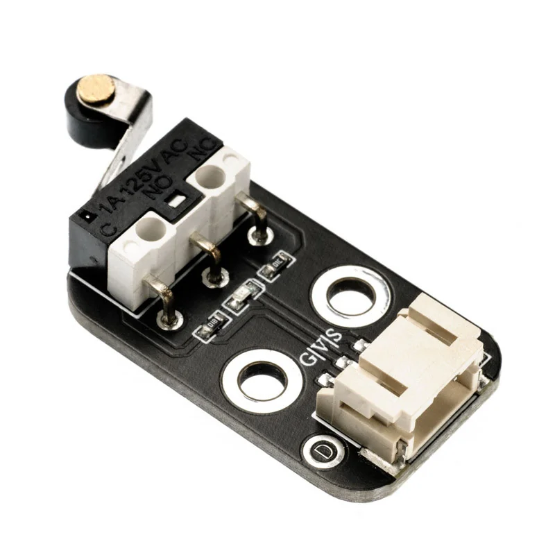
Mechanical Endstop Limit Switch Module HS-S31p - 3-Pin Connector, Precision Detection for 3D Printers and CNC Machines
: Vous pouvez voir les tarifs d'expédition et estimations de livraison cliquant ici
: Retour sous 7 jours avec conditions, cliquez pour plus de détails
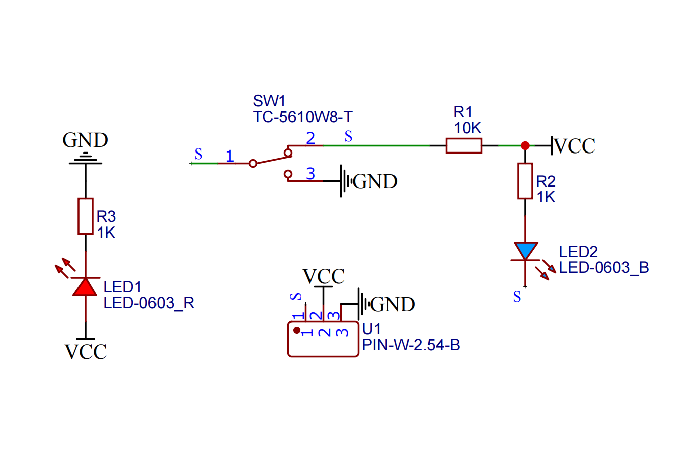
2. Schematic diagram

3. Module parameters
| Pin Name | describe |
|---|---|
| G | GND (negative pole of power input) |
| V | VCC (power input positive) |
| S | Digital signal pins |
Supply voltage: 3.3V / 5V
Connection method: PH2.0 terminal line
Installation method: double screw fixing
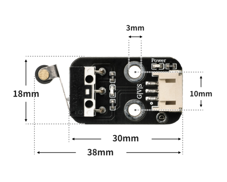
4. Circuit board size
Sample program (UNO development board):
int limitswitchPin = 4; //Set the collision switch to pin D4 int led = 6; //Set the LED light to D6 pin void setup() { Serial.begin(9600); //Set the serial port baud rate pinMode(limitswitchPin, INPUT); //Set the collision switch to input mode pinMode(led, OUTPUT); //Set led to output mode } void loop() { //Connect the collision switch to the D4 pin of the uno development board; connect the LED light module to the D6 pin if (digitalRead(limitswitchPin) == LOW) {//Press the collision switch Serial.println("Trigger the switch and light up the LED for 1 second"); digitalWrite(led, HIGH);//Light up the LED delay(1000); //delay 1S } else { Serial.println("No switch is triggered, LED is off"); digitalWrite(led, LOW); //Turn off LED } delay(500); }
Sample program (ESP32 development board - based on Python language, can not use Arduino IDE to upload code):
import machine import time pin2 = machine.Pin(2, machine.Pin.IN) pin4 = machine.Pin(4, machine.Pin.OUT) while True: if pin2.value() == 0: pin4.value(1) time.sleep(1) else: pin4.value(0)
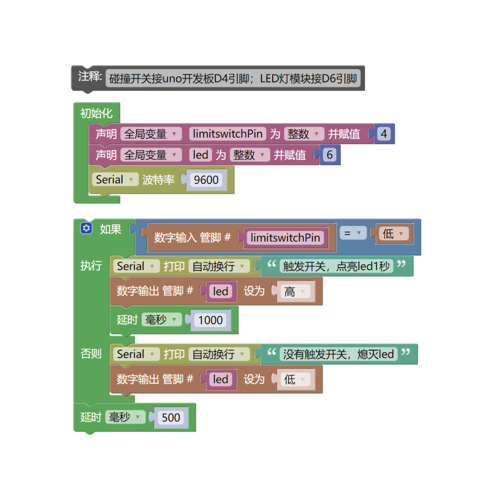
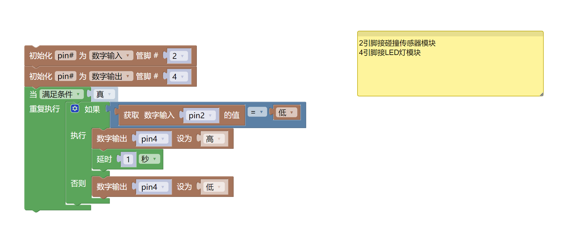
6. Mixly sample program (graphical language)
Sample program (UNO development board):
Sample program (ESP32 development board)
7. Test environment construction
Arduino environment construction
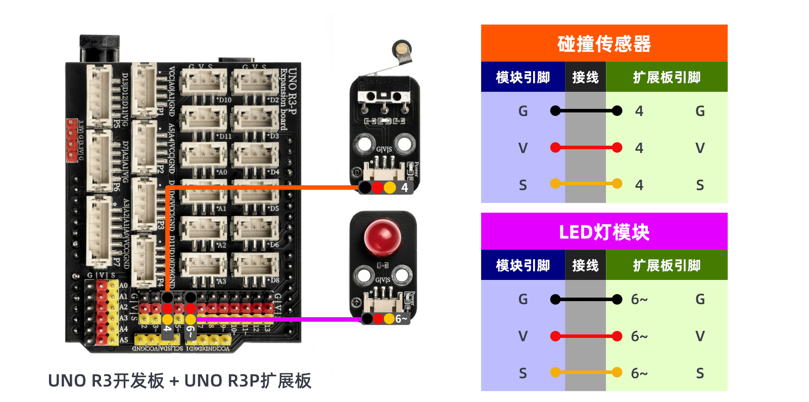
Prepare accessories:
- HELLO STEM UNO R3 development board*1
- HELLO STEM UNO R3 P expansion board*1
- USB type-c data cable*1
- LED light module (HS-F08P)*1
- Collision sensor module (HS-S31P)*1
- PH2.0 3P terminal to Dupont cable*2 or PH2.0 3P double-ended terminal cable*2
Circuit wiring diagram:
Micropython environment construction
Prepare accessories:
Circuit wiring diagram:
8. Video Tutorials
Video tutorial:
9. Test conclusion
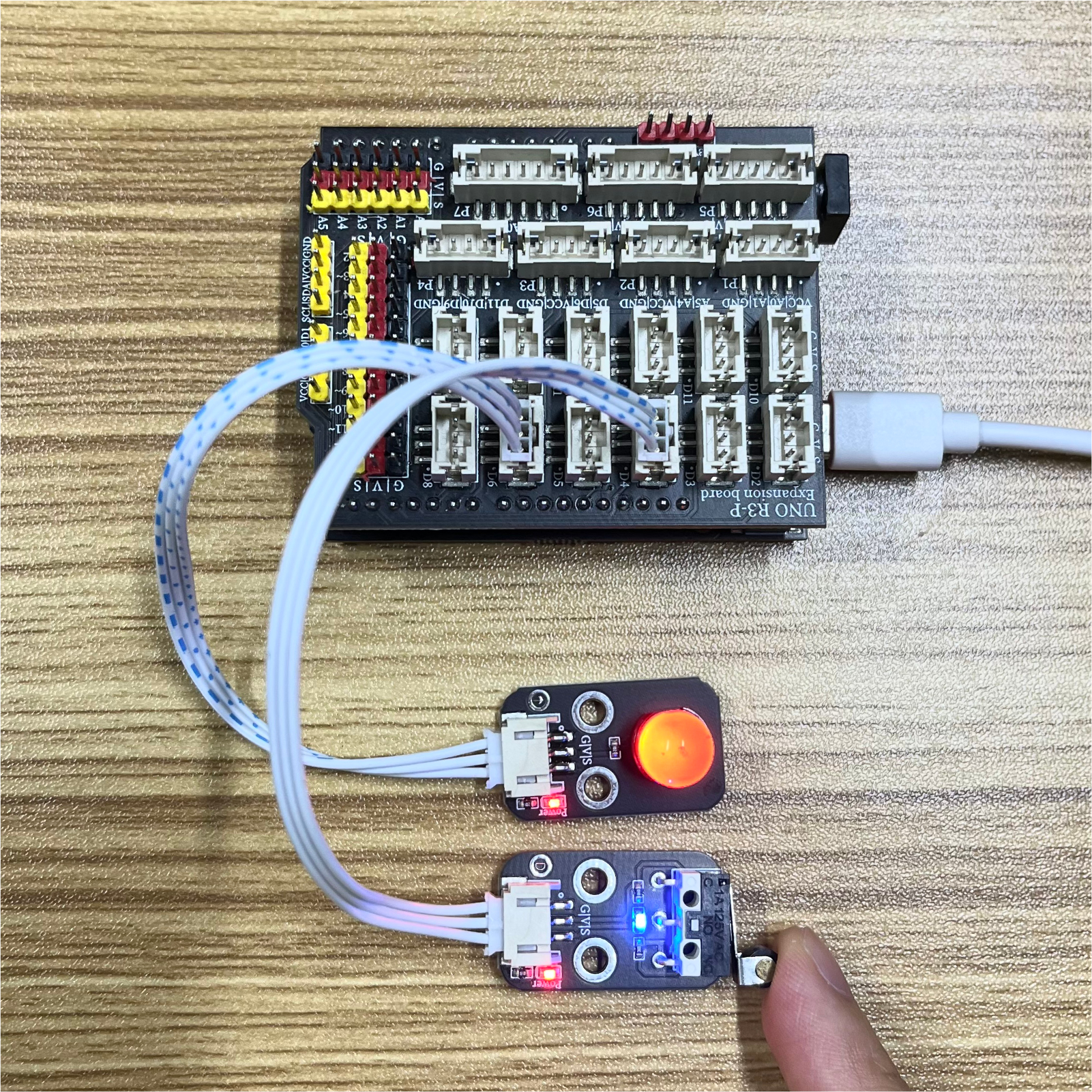
When the collision switch module is hit, the signal port of the collision switch module will output a low level. By judging the high and low level states of the signal port, the LED light is controlled to turn on and off. After the device is connected, burn the above program to the Arduino UNO development board, power on the mainboard, press the touch switch, the LED light turns on for 1 second, and the light turns off when it is released, achieving the purpose.
Avis clients vérifiés
Expériences réelles de clients ayant acheté ce produit
Aucun avis pour le moment.
Description & retour
2. Schematic diagram

3. Module parameters
| Pin Name | describe |
|---|---|
| G | GND (negative pole of power input) |
| V | VCC (power input positive) |
| S | Digital signal pins |
Supply voltage: 3.3V / 5V
Connection method: PH2.0 terminal line
Installation method: double screw fixing
4. Circuit board size

Sample program (UNO development board):
int limitswitchPin = 4; //Set the collision switch to pin D4 int led = 6; //Set the LED light to D6 pin void setup() { Serial.begin(9600); //Set the serial port baud rate pinMode(limitswitchPin, INPUT); //Set the collision switch to input mode pinMode(led, OUTPUT); //Set led to output mode } void loop() { //Connect the collision switch to the D4 pin of the uno development board; connect the LED light module to the D6 pin if (digitalRead(limitswitchPin) == LOW) {//Press the collision switch Serial.println("Trigger the switch and light up the LED for 1 second"); digitalWrite(led, HIGH);//Light up the LED delay(1000); //delay 1S } else { Serial.println("No switch is triggered, LED is off"); digitalWrite(led, LOW); //Turn off LED } delay(500); }
Sample program (ESP32 development board - based on Python language, can not use Arduino IDE to upload code):
import machine import time pin2 = machine.Pin(2, machine.Pin.IN) pin4 = machine.Pin(4, machine.Pin.OUT) while True: if pin2.value() == 0: pin4.value(1) time.sleep(1) else: pin4.value(0)
6. Mixly sample program (graphical language)
Sample program (UNO development board):

Sample program (ESP32 development board)

7. Test environment construction
Arduino environment construction
Prepare accessories:
- HELLO STEM UNO R3 development board*1
- HELLO STEM UNO R3 P expansion board*1
- USB type-c data cable*1
- LED light module (HS-F08P)*1
- Collision sensor module (HS-S31P)*1
- PH2.0 3P terminal to Dupont cable*2 or PH2.0 3P double-ended terminal cable*2
Circuit wiring diagram:

Micropython environment construction
Prepare accessories:
Circuit wiring diagram:
8. Video Tutorials
Video tutorial:
9. Test conclusion

When the collision switch module is hit, the signal port of the collision switch module will output a low level. By judging the high and low level states of the signal port, the LED light is controlled to turn on and off. After the device is connected, burn the above program to the Arduino UNO development board, power on the mainboard, press the touch switch, the LED light turns on for 1 second, and the light turns off when it is released, achieving the purpose.
Politique de retour Websoog
Si vous n'êtes pas satisfait d'un produit acheté sur websoog.com, ou si celui-ci est défectueux ou endommagé, vous pouvez le retourner dans les 8 jours suivant la date de livraison, et nous procéderons à son remplacement. Veuillez noter que si la commande dépasse ce délai, nous ne pourrons pas accepter le retour. Les produits sont échangés uniquement, aucun remboursement n'est effectué.
Échange possible si le produit ne correspond pas à l'image ou à la description.
Nous traitons les anomalies, défauts, produits endommagés ou pièces manquantes.
Une vidéo complète permet de protéger vos droits et d'accélérer le traitement.
Conditions pour échanger un produit
- Si le produit ne correspond pas à l'image présentée sur le site.
- Si le produit présente un défaut ou une anomalie.
- Si le produit est endommagé.
- Si le produit est une contrefaçon.
- Si le produit manque certaines de ses pièces.
- Si vous n'êtes pas satisfait du produit, sans que les raisons mentionnées ci-dessus soient en cause, les frais de retour seront à votre charge.
Conditions vidéo pour garantir votre droit de retour et d'échange
Pour protéger vos droits et éviter tout malentendu, merci de respecter les étapes suivantes :
- Filmez le colis avant ouverture pour montrer l’état de l’emballage extérieur.
- Assurez-vous que l’étiquette avec votre nom et adresse soit bien visible dans la vidéo.
- Enregistrez l’intégralité de l’ouverture du colis, sans interruption, jusqu’à ce que le produit soit entièrement sorti.
- Une fois le produit sorti, filmez-le sous tous les angles.
- Si le produit est électronique, montrez son fonctionnement et ses fonctionnalités principales dans la vidéo.
- Si des défauts, anomalies ou pièces manquantes sont constatés, filmez-les clairement.
Méthodes pour échanger un produit
Lors de la réception du nouveau produit, vous devrez payer un montant spécifique en garantie. Remettez l'ancien produit au bureau de livraison au moment où vous recevez le nouveau produit. Une fois le produit retourné reçu, nous inspecterons son état. Si le produit est en bon état, le montant de la garantie sera restitué. Si le produit est en mauvais état, une déduction sera effectuée sur la garantie, en fonction de l’état du produit.
Vous envoyez le produit pour inspection. Après vérification de son état, un produit de remplacement vous sera envoyé. Cette méthode prend plus de temps.
Produits non éligibles à l'échange
- Produits ouverts qui ne peuvent pas être retournés pour des raisons d'hygiène ou de santé.
- Enregistrements audio/vidéo ou logiciels ouverts après livraison.
- Produits personnalisés ou fabriqués sur commande.
- Produits susceptibles de se détériorer rapidement.
- Contenu numérique non fourni sur support matériel (CD, DVD, etc.).
- Produits volumineux nécessitant un montage, comme les meubles.
Connectez-vous à votre compte via le lien suivant : Connexion à votre compte. Remplissez ensuite le formulaire de demande de retour en y ajoutant la vidéo comme preuve.
Avis clients vérifiés
Expériences réelles de clients ayant acheté ce produit
Aucun avis pour le moment.
2. Schematic diagram

3. Module parameters
| Pin Name | describe |
|---|---|
| G | GND (negative pole of power input) |
| V | VCC (power input positive) |
| S | Digital signal pins |
Supply voltage: 3.3V / 5V
Connection method: PH2.0 terminal line
Installation method: double screw fixing
4. Circuit board size

Sample program (UNO development board):
int limitswitchPin = 4; //Set the collision switch to pin D4 int led = 6; //Set the LED light to D6 pin void setup() { Serial.begin(9600); //Set the serial port baud rate pinMode(limitswitchPin, INPUT); //Set the collision switch to input mode pinMode(led, OUTPUT); //Set led to output mode } void loop() { //Connect the collision switch to the D4 pin of the uno development board; connect the LED light module to the D6 pin if (digitalRead(limitswitchPin) == LOW) {//Press the collision switch Serial.println("Trigger the switch and light up the LED for 1 second"); digitalWrite(led, HIGH);//Light up the LED delay(1000); //delay 1S } else { Serial.println("No switch is triggered, LED is off"); digitalWrite(led, LOW); //Turn off LED } delay(500); }
Sample program (ESP32 development board - based on Python language, can not use Arduino IDE to upload code):
import machine import time pin2 = machine.Pin(2, machine.Pin.IN) pin4 = machine.Pin(4, machine.Pin.OUT) while True: if pin2.value() == 0: pin4.value(1) time.sleep(1) else: pin4.value(0)
6. Mixly sample program (graphical language)
Sample program (UNO development board):

Sample program (ESP32 development board)

7. Test environment construction
Arduino environment construction
Prepare accessories:
- HELLO STEM UNO R3 development board*1
- HELLO STEM UNO R3 P expansion board*1
- USB type-c data cable*1
- LED light module (HS-F08P)*1
- Collision sensor module (HS-S31P)*1
- PH2.0 3P terminal to Dupont cable*2 or PH2.0 3P double-ended terminal cable*2
Circuit wiring diagram:

Micropython environment construction
Prepare accessories:
Circuit wiring diagram:
8. Video Tutorials
Video tutorial:
9. Test conclusion

When the collision switch module is hit, the signal port of the collision switch module will output a low level. By judging the high and low level states of the signal port, the LED light is controlled to turn on and off. After the device is connected, burn the above program to the Arduino UNO development board, power on the mainboard, press the touch switch, the LED light turns on for 1 second, and the light turns off when it is released, achieving the purpose.